Audi TT MK1 (8N) infotainment
Chorus/Concert radios, CD/cassette player, CD changer, iPod adapter and Bose sound.
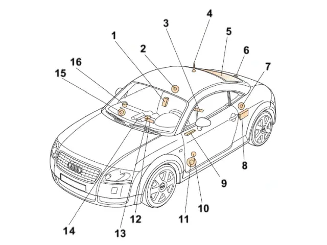
| Number | Component / Function |
|---|---|
| 1 | 4-channel equaliser amplifier (Bose) |
| 2 | Rear speaker (Bose) |
| 3 | J412 - Telephone electronics control unit (on the rear floor frame) |
| 4 | Phone Antenna |
| 5 | Radio aerial in the rear window |
| 6 | Antenna amplifier in the tailgate |
| 7 | Rear speaker (Bose) |
| 8 | CD changer |
| 9 | Telephone or preparation |
| 10 | Speaker: tweeter |
| 11 | Speaker: bass |
| 12 | R - Car radio |
| 13 | Central speaker (left defrost nozzle) |
| 14 | Navigation system receiver |
| 15 | Speaker: bass |
| 16 | Speaker: tweeter |
Audi Chorus and Concert radios
There was no car radio in the series. The Chorus and Concert radios were available as options, both equipped with a first-generation cassette player. The Concert, however, offered improved sound and amplification.
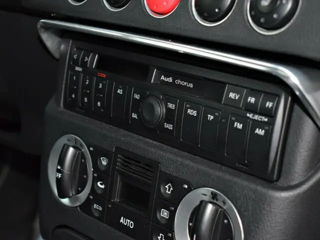
Chorus - Generation I
Radio/Cassette
No external device connection
Production: 1998 – 2001
Cannot add a CD changer or iPod adapter later.
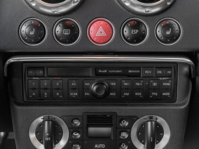
Concert - Generation I
Radio/Cassette
External device connection
Production: 1998 – 2001
Cannot add a CD changer or iPod adapter later.
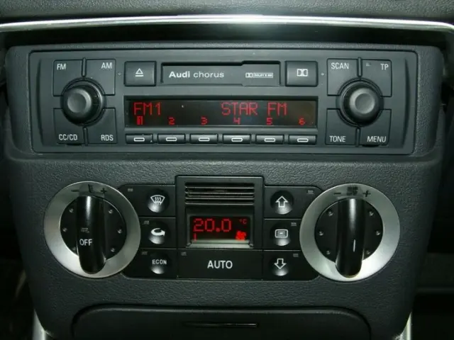
Chorus - Generation II
Radio/Cassette
External device connection
Production 2002 – 2006
Compatible with the later addition of a CD changer and an iPod adapter.
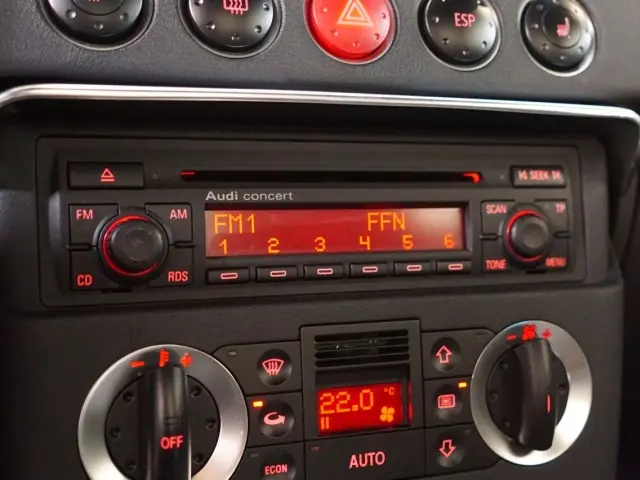
Concert - Generation II
Radio/Single CD Player
External device connection
Production : 2002 – 2006
Compatible with the later addition of a CD changer and an iPod adapter.
External devices
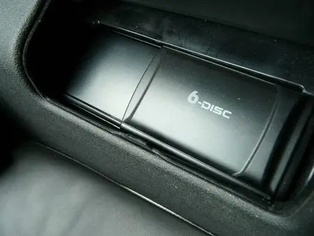
CD changer
Installed in the rear left storage panel
Production: 1998 – 2006
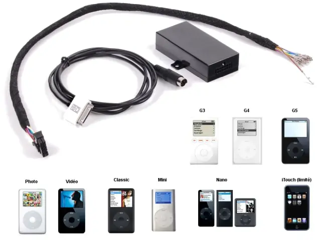
iPod adapter
Can be installed on vehicles equipped with a Generation 2 car radio.
Cannot be used with an automatic changer (or other external device).
Bose Sound System
The Bose Sound System delivers an exceptional sound experience. It consists of a dedicated amplifier and several speakers optimized for the passenger compartment, offering a powerful and balanced sound, specially designed for the coupe and the roadster.
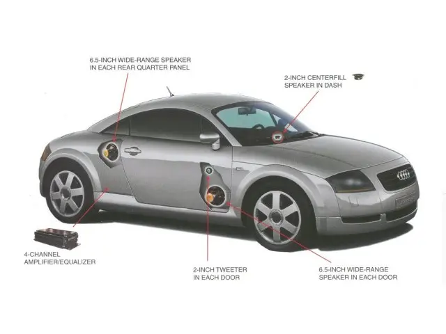
Bose Sound System on Coupe
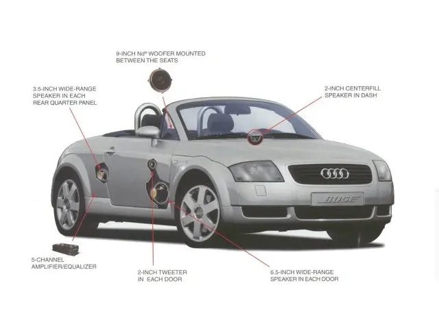
Bose Sound System on Roadster
Navigation system
The Basic Navigation System (BNS) is a simple and functional integrated navigation system produced between 1998 and 2003. It uses a monochrome display in the onboard computer (FIS), supplemented by voice instructions.
Routes are calculated from mapping CDs, and commands pass through the Chorus/Concert radio block. Minimalist but effective, it offers a discreet and integrated navigation aid, long before the era of touch-sensitive GPS.
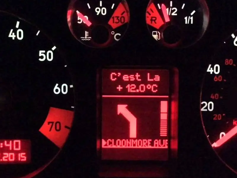
BNS - Monochrome display
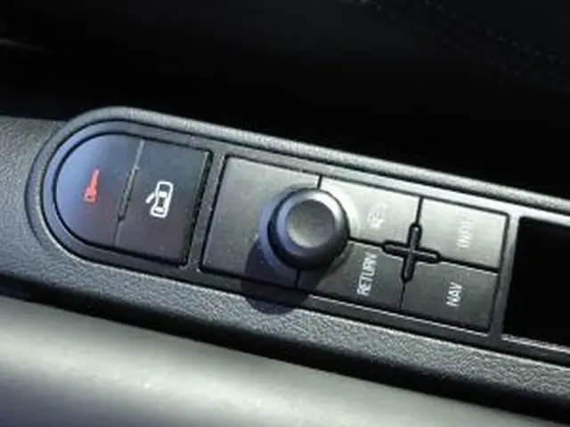
BNS - Control Module
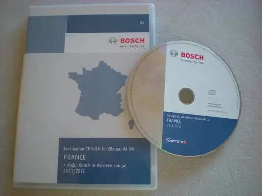
BNS - Mapping CD
Telephone pre-equipment
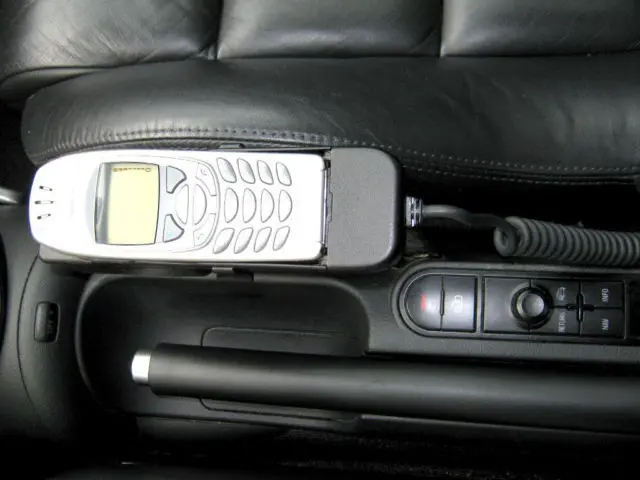
Generation I
The first generation pedestals are connected to the system by a cable.
The base keeps the phone charged. The bases are specific to each model of phone.
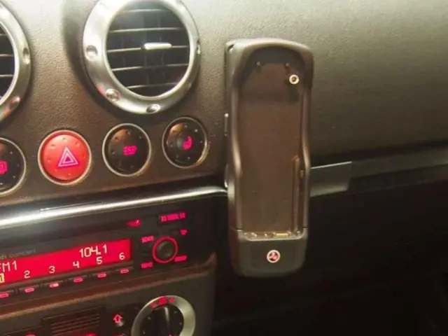
Generation II
The second-generation pedestals are cable-free, but have a gold-plated band on the base.
The bases are specific to each model of phone.
Wiring diagram
Car Radio Connectors - Gen I and II
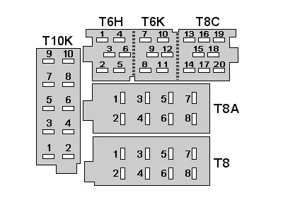
Chorus and Concert Connectors
| Connector | Function |
|---|---|
| T10K | Phone and Navigation |
| T6H | Amplifier |
| T6K | Bus CAN |
| T8C | CD changer |
| T8A | Speakers |
| T8 | Power supply |
Chorus and Concert radio wiring - Gen II
Cable cabling and colors may vary slightly depending on the model and years. It is therefore recommended to check the specific drawings for your vehicle for accurate identification.
The chart below is the wiring of a 2002 Model Year Concert 2 with the Bose Sound System, CD Changer, Phone and Navigation System options.
| Number | Function | Colour |
|---|---|---|
T8 connector - Power supply |
||
| 1 | Bose coding (earth) | Brown |
| 2 | Anti-theft alarm earth | Brown/Grey |
| 3 | Diagnostic line | Grey/White |
| 4 | - | |
| 5 | - | |
| 6 | - | |
| 7 | Permanent +12V | Red/White |
| 8 | Earth | Brown |
T8A Connector - Speakers |
||
| 1 | - | - |
| 2 | - | - |
| 3 | - | - |
| 4 | - | - |
| 5 | - | - |
| 6 | - | - |
| 7 | - | - |
| 8 | - | - |
T6H connector - Amplifier |
||
| 1 | - | - |
| 2 | - | - |
| 3 | Audio signal earth | Brown |
| 4 | Left Front Signal | Green |
| 5 | Front right signal | Grey/White |
| 6 | Ignition-switched +12V | Black |
T6K connector - CAN bus |
||
| 7 | CAN High | Orange/Violet |
| 8 | - | - |
| 9 | - | - |
| 10 | CD changer earth | Brown |
| 11 | - | - |
| 12 | CAN Low | Orange/Brown |
T8C connector - CD changer |
||
| 13 | Data In | Orange |
| 14 | Data Out (to CD changer) | Red |
| 15 | Data synchronisation | Black |
| 16 | Permanent +12V | Blue |
| 17 | Ignition-switched +12V | Yellow |
| 18 | Earth | (NCA- black) |
| 19 | Left audio line | White |
| 20 | Right audio line | Red |
Connector T10K - Phone and Navigation |
||
| 1 | Mute Phone | Grey |
| 2 | - | - |
| 3 | Audio Telephone (+) | Yellow |
| 4 | Telephone audio (–) | Green |
| 5 | Audio navigation (+) | Blue/Red |
| 6 | Audio navigation (-) | Brown/Red |
| 7 | Navigation Command Line | Red/Green |
| 8 | - | - |
| 9 | - | - |
| 10 | - | - |