Air conditioning of the Audi TT MK1 (8N)
Compressor with electromagnetic clutch, condenser, evaporator and expansion valve.
Refrigerant circuit
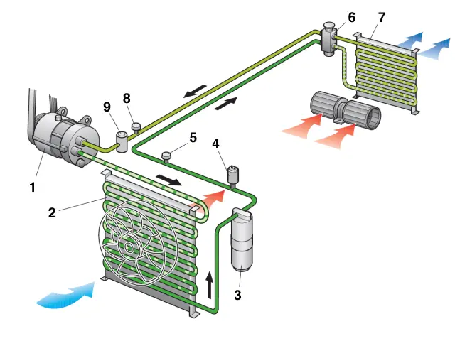
| Number | Function |
|---|---|
| 1 | Compressor with N25 - electromagnetic clutch |
| 2 | Condenser |
| 3 | Receiver-drier |
| 4 | G65 - High-pressure switch |
| 5 | High-pressure service connection |
| 6 | Expansion valve |
| 7 | Evaporator |
| 8 | Low-pressure service connection |
| 9 | Damper |
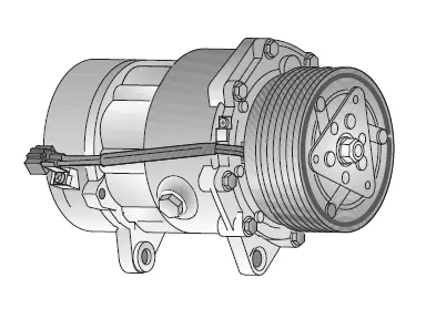
Compressor with electromagnetic clutch
The compressor only works when the air conditioner is in circuit, this operation being controlled by an electromagnetic clutch.
The compressor raises the pressure of the refrigerant, the temperature of which increases. Without this pressure rise, further expansion and thus cooling of the refrigerant in the air conditioner would not be possible.
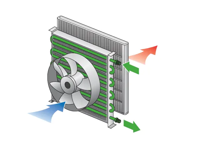
Condenser
The condenser is the "radiator" of the air conditioner.
Hot refrigerant in gaseous form enters through the top of the condenser. The tubes and fins of the condenser absorb heat. Fresh outdoor air is directed above the condenser, it absorbs heat and the gaseous refrigerant is cooled.
During cooling, the refrigerant condenses at a given temperature and passes into the liquid state and flows through the bottom of the condenser.
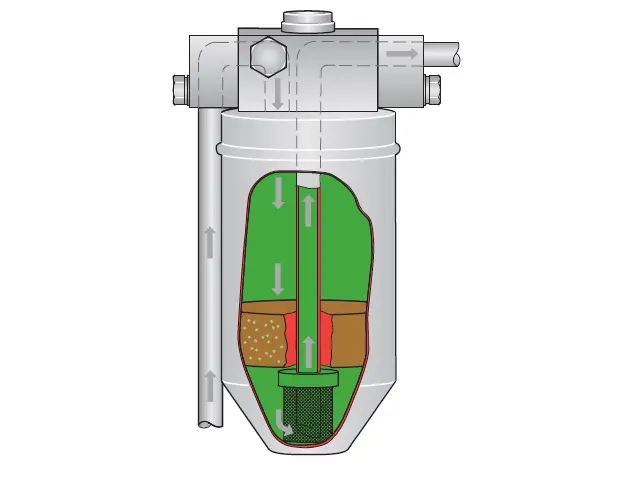
Receiver-drier
The liquid tank serves, in the refrigerant circuit equipped with a expansion valve, expansion vessel and refrigerant tank. In case of different service conditions such as heat stress at the evaporator and condenser, compressor speed, the amount of refrigerant pumped into the circuit varies.
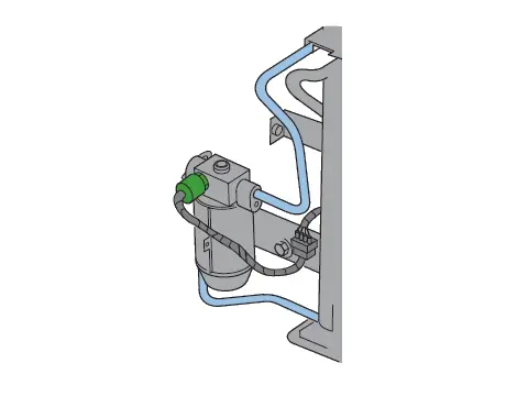
G65 - High-pressure switch
A high-pressure contactor and a low-pressure contactor are mounted on the high-pressure side to monitor and limit pressures in the closed refrigerant circuit.
In case of illicit pressures in the system, the compressor is cut off by the electromagnetic clutch.
The pressure switches can be mounted directly in the pipe or on the liquid tank.
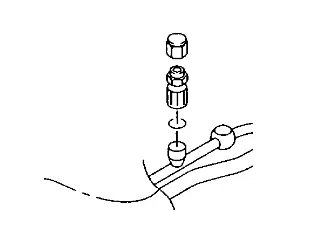
High-pressure service connection
It is used during maintenance work, for the connection of the suction/recycling station for filling, emptying, vacuuming and pressure control.
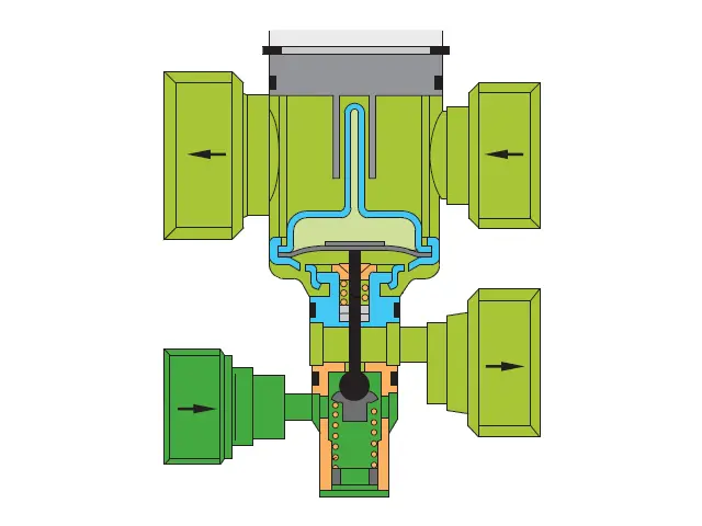
Expansion valve
The expansion valve is where the refrigerant relaxes in the evaporator and cools it. It is the separation between the high pressure side and the low pressure side in the refrigerant circuit.
The expansion valve makes it possible to regulate the flow of refrigerant in the evaporator according to the temperature of the refrigerant vapor at the outlet of the evaporator.
In the evaporator, the expansion of the refrigerant takes place only for the quantity necessary to maintain a homogeneous "cold climate" in the evaporator.
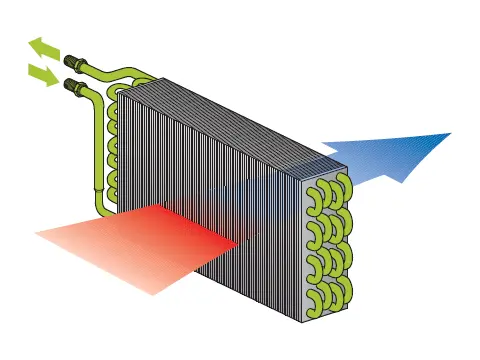
Evaporator
The refrigerant released by the expansion valve is expanded in the evaporator, which then cools sharply and is converted into gas by boiling.
When boiling in the evaporator, temperatures are significantly lower than the freezing point of the water.
The refrigerant takes from its environment the heat necessary for evaporation in the air passing through the evaporator. This "cooled" air is conveyed into the passenger compartment.
The humidity of the cooled air is deposited in the evaporator at places where the temperature is lower than the dew point, which is equivalent to saying that it condenses. Condensing water is produced. The air is "dried."
The climate in the cabin is optimized and a healthy air is quickly obtained. Suspended particles in the air also settle with moisture on the evaporator. The evaporator also "cleans" the air.
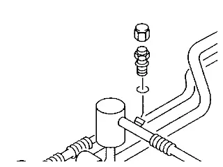
Low-pressure service connection
It is used during maintenance work, for the connection of the suction/recycling station for filling, emptying, vacuuming and pressure control.
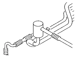
Damper
Some systems have a damper upstream of the compressor to reduce refrigerant vibrations.
System Components
An air conditioner only works if all components of the system work properly. In the event of a component failure, operating pressures may be changed and subsequent damage to the system and the engine cannot be excluded. To avoid these problems, monitoring devices have been implanted in the refrigerant circuit.
A control unit processes the signals and controls the periodic switching on and off of the compressor and the blower speed. This allows the establishment of a pressure level in the refrigerant circuit that is always at normal values.
The signals of the monitoring system are also, on systems equipped with an unregulated compressor, used for the adaptation to the needs of refrigerating capacity.
(Cutting and turning on the air conditioner according to cold needs. This simultaneously prevents icing of the evaporator).
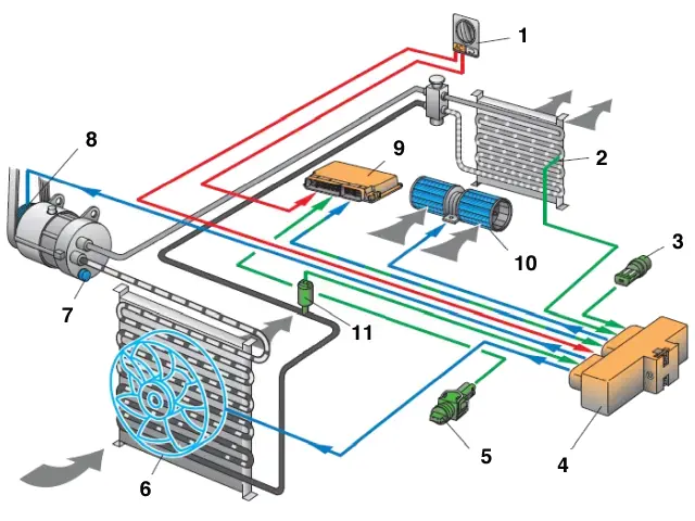
| Number | Function |
|---|---|
| 1 | E87 - Control and display unit |
| 2 | G153 - Evaporator temperature transmitter |
| 3 | F18 - Coolant fan thermal switch |
| 4 | J293 - Air conditioner and coolant fan control unit |
| 5 | G62 - Coolant temperature transmitter |
| 6 | V7 - Coolant fan |
| 7 | Pressure relief valve on compressor |
| 8 | N25 - Electromagnetic clutch |
| 9 | J220 - Engine control unit |
| 10 | V2 - Fresh air blower |
| 11 | G65 - Air conditioner pressure switch |
E87 - Control and display unit
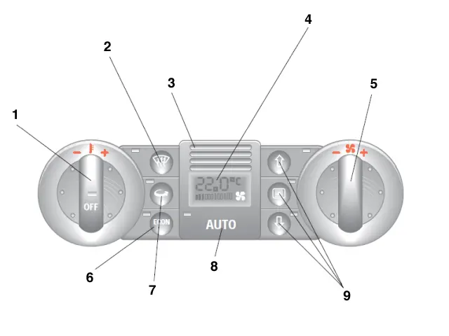
| Number | Function |
|---|---|
| 1 | Air conditioning on/off (pull/push control) and temperature adjustment (warmer/colder rotary control) |
| 2 | De-icing key for windscreens and side windows |
| 3 | G56 - Temperature sensor and V42 - Temperature sensor blower |
| 4 | Display area for operating conditions, fan speeds, desired indoor temperature |
| 5 | Rotary switch Blower speed regulation (air flow regulation) |
| 6 | Economy mode. Compressor switched off |
| 7 | Air recirculation button |
| 8 | Automatic mode |
| 9 | Distribution of air |
When the “de-icing” button is activated, the air recirculation mode is automatically left.
Climatronic
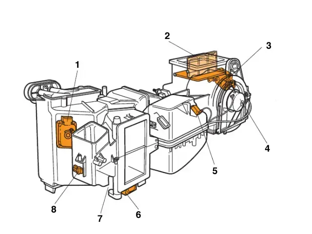
| Component | Function |
|---|---|
| 1 | V85 - Servomotor for floor flap / defrosting |
| 2 | G89 - Temperature sensor - fresh air intake channel |
| 3 | V71 - Servomotor for dynamic pressure flap |
| 4 | V2 - Fresh air blower |
| 5 | J126 - Control unit for fresh air blowers |
| 6 | V70 - Servomotor for central flap |
| 7 | V68 - Servomotor for temperature shutter |
| 8 | G192 - Temperature transmitter to air diffuser on the floor |
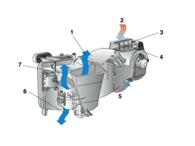
| N° | Function |
|---|---|
| 1 | Dashboard air outlets (left - right - centre) |
| 2 | Fresh Air Entry |
| 3 | Dynamic pressure valve |
| 4 | Fresh/Recycled Air Shutter |
| 5 | Recycled Air Inlet |
| 6 | Footwell air outlets |
| 7 | Defrosting |
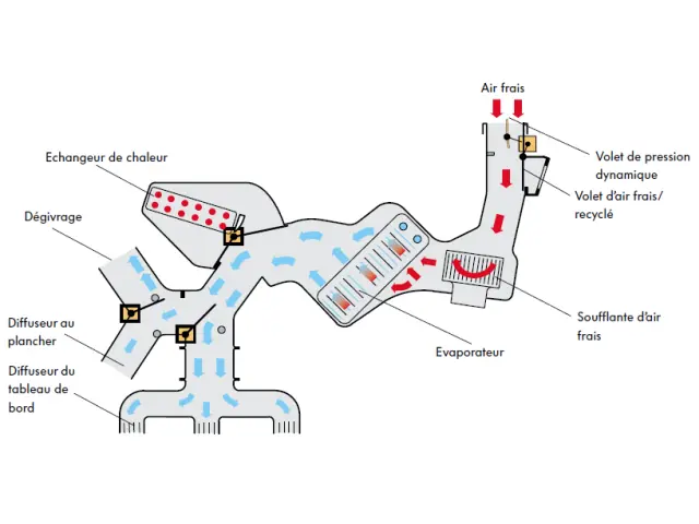
Air Conditioning Mode
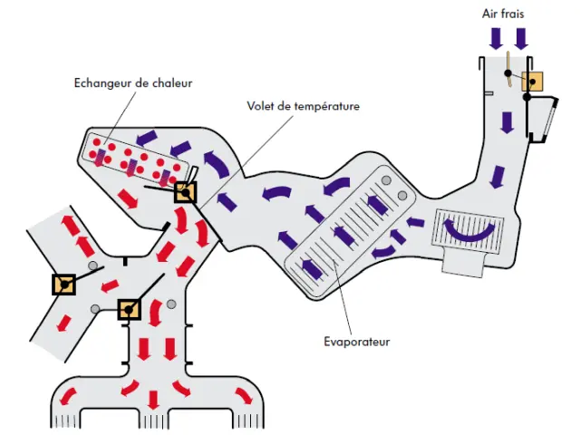
Heating mode
Synoptic of the system
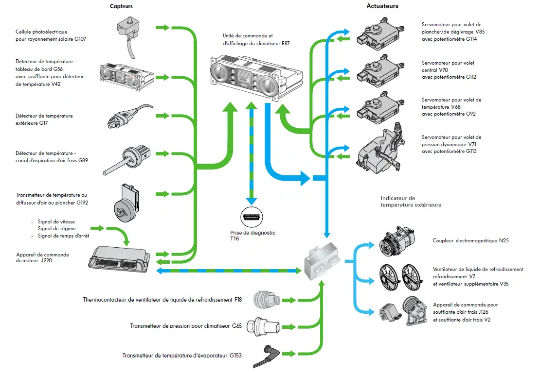
Functions of the sensors
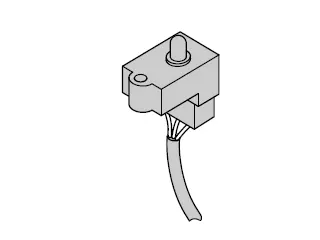
G107 - Photoelectric cell for solar radiation
It records direct solar radiation on the occupants of the vehicle.
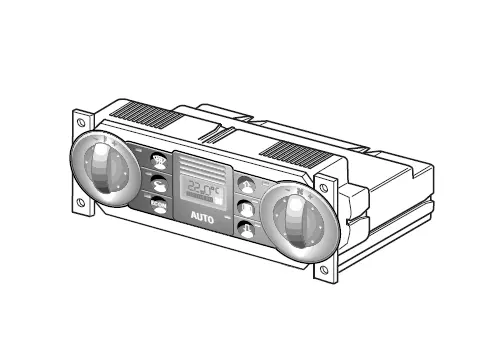
G56 - Dashboard temperature sensor
It is mounted directly on the control unit and provides it with the actual temperature of the cabin.
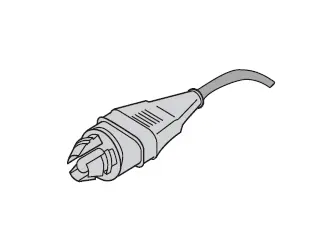
G17 - Outdoor temperature sensor
It is located at the front of the vehicle and records and transmits to the control unit the actual outside temperature.
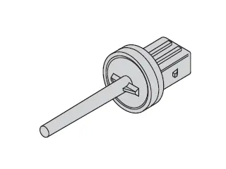
G89 - Temperature sensor - fresh air intake channel
The temperature sensor is placed in the air conditioner, directly in the fresh air intake channel. This is the second real outdoor temperature measurement point.
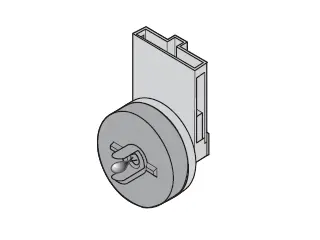
G192 - Temperature transmitter to air diffuser on the floor
The temperature detector is placed in the air conditioner, it measures the temperature of the air coming out of the air conditioner to go into the cabin.
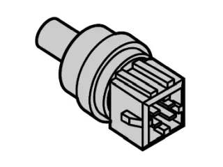
G62 - Coolant temperature transmitter
It indicates the temperature of the coolant to the engine control unit (J220) which transmits it to the air conditioner and coolant fan control unit (J293).
In case of too high temperatures of the coolant, the J293 switches off the compressor.
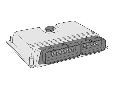
J220 - Engine control unit
It communicates (bidirectional signal exchange) with the control and display unit (E87) and the air conditioner and coolant fan control unit (J293)
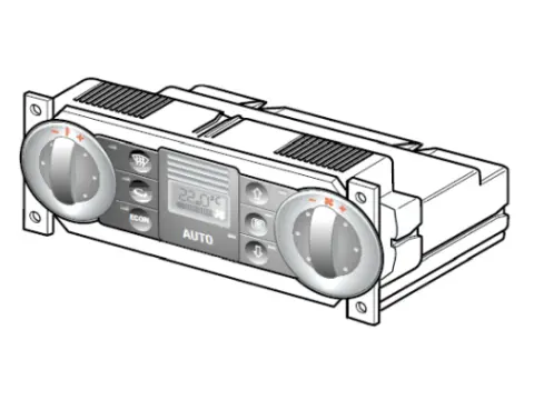
E87 - Control and display unit
It transmits the driver's instructions to:
- the air conditioner and coolant fan control unit (J293);
- the engine control unit (J220).
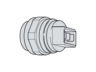
F18 - Coolant fan thermal switch
It informs the control unit of the air conditioner and coolant fan (J293) when the coolant reaches a high temperature.
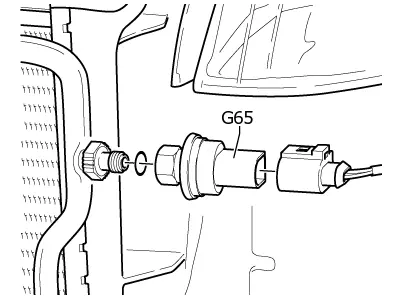
G65 - Pressure transmitter for air conditioner
It detects the engine stress due to the air conditioner and the pressure conditions in the refrigerant circuit.
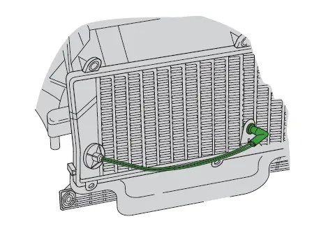
G153 - Evaporator temperature transmitter
It indicates the temperature between the evaporator fins at the air conditioner control unit (J293).
In case of too low temperatures of the evaporator, the J293 switches off the compressor.
Functions of Actuators
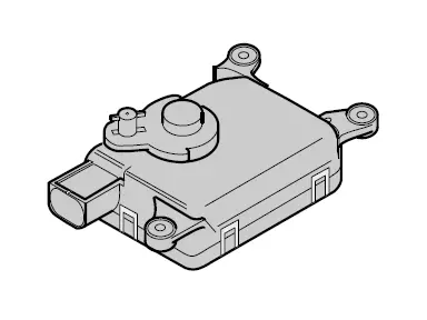
V85 - Servomotor for floor/defrost flap with G114 potentiometer
It directs the air flow to the floor or to the windshield.
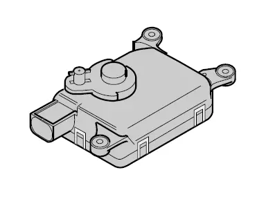
V70 - Servomotor for central flap with potentiometer G112
It directs airflow towards the dashboard air outlets
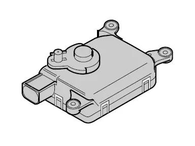
V68 - Servomotor for temperature shutter with potentiometer G92
In the climatronic, it directs air flow to the heat exchanger.
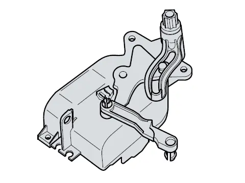
V71 - Servomotor for dynamic pressure flap and recycled air flap with G113 potentiometer
Within the climatronic, it opens/closes the channel of fresh air or recycled air.
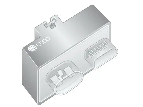
J293 - Control unit for coolant fan
It controls the electromagnetic clutch (N25), the cooling and additional liquid fans (V7 and V35) and the fresh air blower (J126).
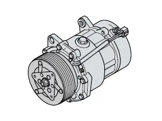
N25 - Electromagnetic clutch
It allows to activate the air conditioning compressor. The compressor raises the pressure of the refrigerant, whose temperature increases.
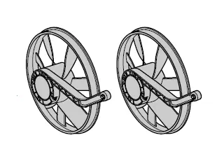
V7 - Coolant fan and V35 - additional fan
The motor control unit (J220) triggers the fan(s).
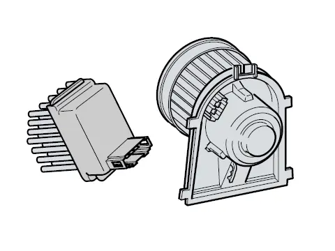
V2 - Fresh air blower and J126 - Control unit for fresh air blowers
It allows the flow of air through the climatronic to send it to the passenger compartment.