Audi TT MK1 (8N) Motronic System
Electronic management of Motronic injection, ignition and sensors for engine reliability.
The Motronic 7.5 system is an electronic engine management system, it is also known as the Motronic ME 7.5. It monitors engine performance by monitoring and adjusting various parameters such as the amount of air and fuel injected into the engine cylinders, ignition and exhaust emissions. The system is programmed with specific electronic boards for each type of engine, allowing for performance optimization and reduced fuel consumption.
It is also equipped with an on-board diagnostic system that makes it possible to diagnose any problems related to the engine and correct them quickly.
Synoptic of the system
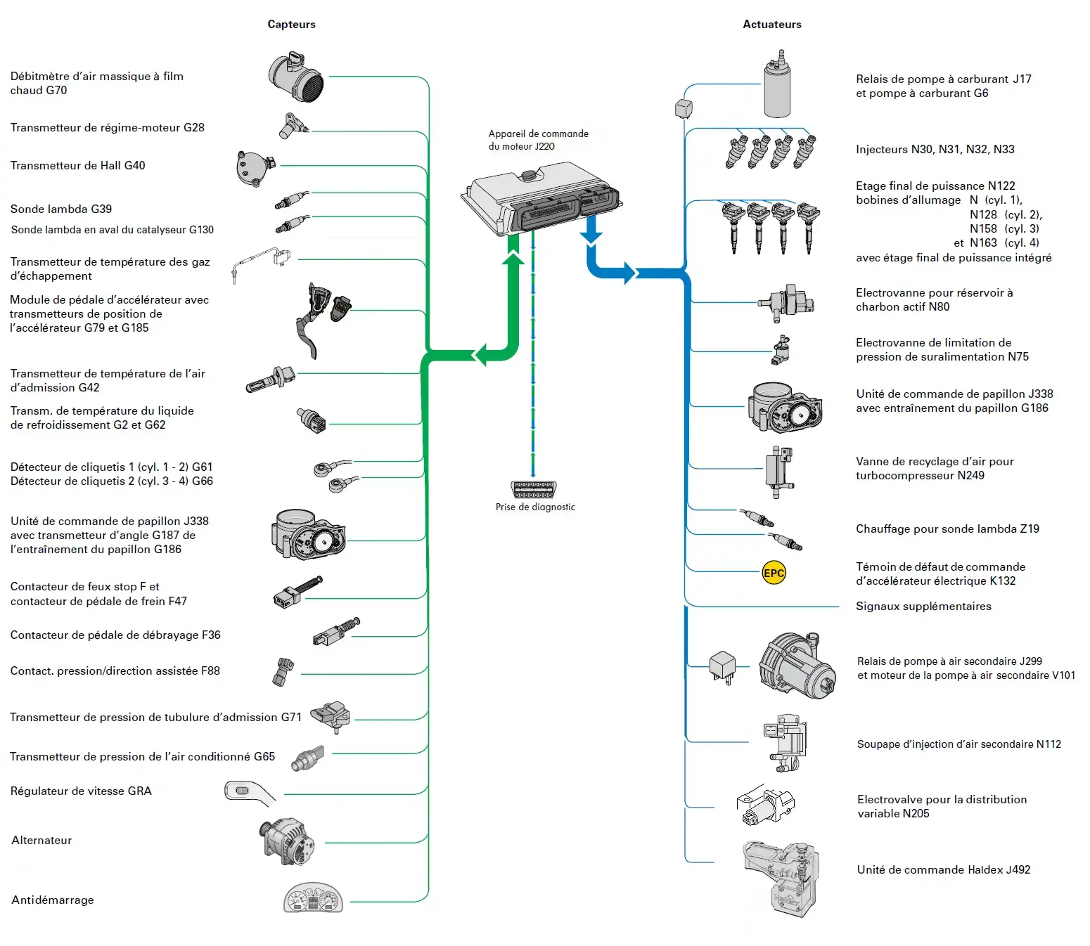
Functions of the sensors
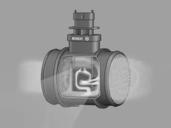
G70 - Hot film mass airflow meter
The hot film mass airflow meter is used to detect the mass of air sucked in. Based on its signal, the engine control unit detects the exact mass of air drawn in.
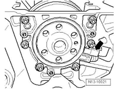
G28 - Engine speed transmitter
The engine speed transmitter signal allows the engine computer to record the engine speed and precise position of the crankshaft. This information is used to calculate the flow rate and the start of injection.
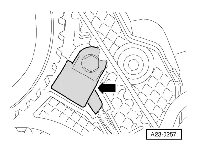
G40 - Hall transmitter
The Hall transmitter is mounted on the cylinder head, under the intake camshaft.
It records the position of an emitting wheel allowing quick start, used for detecting the position of the camshaft.
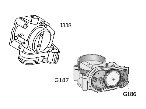
J338 - Throttle body control unit
G187 - angle sensor
G186 - Throttle actuator control unit
Its objective is to regulate the flow of air into the engine in order to obtain an optimal air-fuel ratio for combustion.
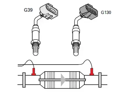
G39 and G130- Lambda sensor
The G39 lambda sensor upstream of the catalytic converter controls the air/fuel mixture.
The downstream lambda probe G130 is used to monitor the operation of the catalyst.
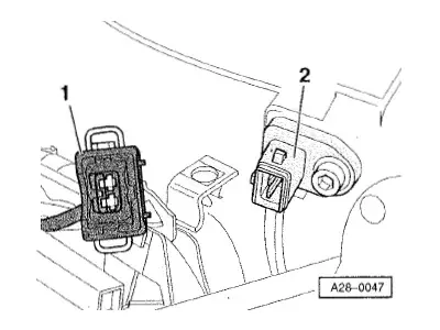
G42 - Intake air temperature transmitter
It measures the temperature in the inlet tubing to allow the computer to act on the formation of the mixture and the ignition angle.
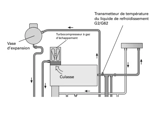
G2 and G62 - Coolant temperature transmitter
The G2 probe informs the instrument cluster, the G62 informs the engine management control unit which uses it in the calculation of the injection rate.
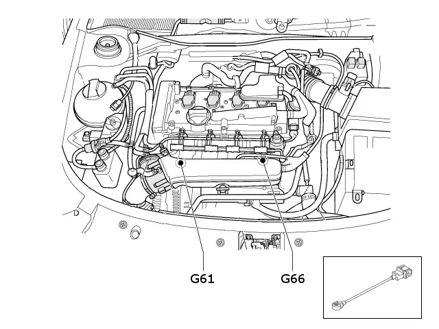
G61 - Knock sensor 1 (cylinders 1 - 2)
G66 - Knock sensor 2 (cylinders 3 - 4)
They detect the vibrations, caused by self-ignition, on the engine block and inform the computer which will increase the delay to the ignition to make disappear this phenomenon.
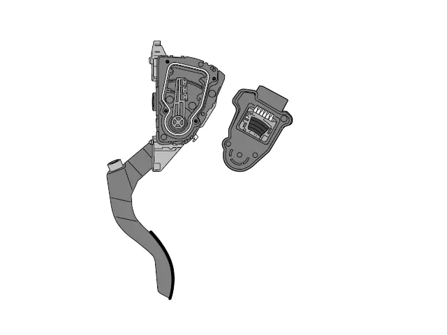
G79 and G185 - Accelerator pedal module with accelerator position transmitters
These 2 potentiometers are independent, they transmit to the control unit the position of the accelerator pedal. In case of failure of one transmitter, the other replaces it.
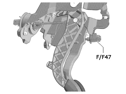
F- Stop light switch
F47- Brake pedal switch
The two sensors are combined in a single component. They are used by the computer to check the position of the accelerator as well as to cancel the speed regulation.
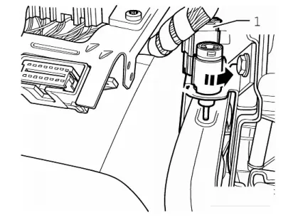
F36 - Clutch pedal switch
It is used by the striker to avoid transmission strokes on acceleration/deceleration phases without disengagement as well as to cancel the speed regulation.
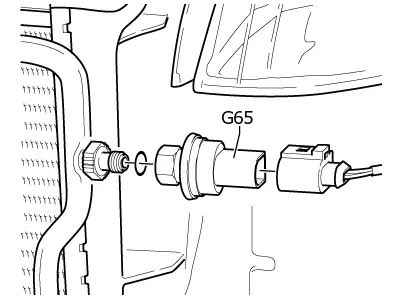
G65- Air conditioning pressure transmitter
It allows the control unit to know the torque consumed by the air conditioning and compensate it by increasing the opening of the throttle via the electronic accelerator.
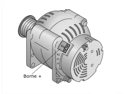
Terminal + dr of the alternator
Through this signal, the control unit identifies the motor torque absorbed by the alternator and compensates for it by opening the throttle via the electronic accelerator.
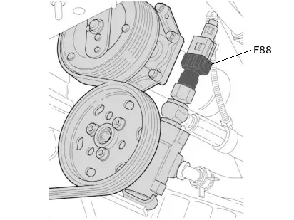
F88 - Power steering pressure switch
It is used by the control unit to improve idle stabilization.
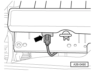
G235 - Exhaust gas temperature transmitter
It is used by the control unit to regulate the temperature of the exhaust gases by enriching the mixture.
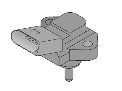
G71 - Intake pipe pressure transmitter
It is used by the control unit to check the opening of the throttle, thus allowing it to identify a possible failure of the electronic accelerator or even an air intake.
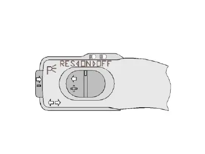
GRA Cruise Control
It is used by the ECU to manage the throttle control unit according to the driver's request.
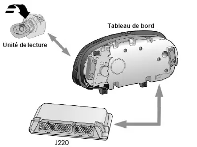
Immobilizer
The immobilizer control unit is integrated into the instrument cluster and used by the ECU to allow start-up.
Functions of Actuators
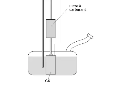
G6 - Fuel pump
The control unit determines the amount of fuel to be injected according to the various parameters it has.
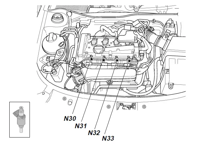
N30, N31, N32, N33 - Injectors
The control unit determines when and how long the injectors operate.
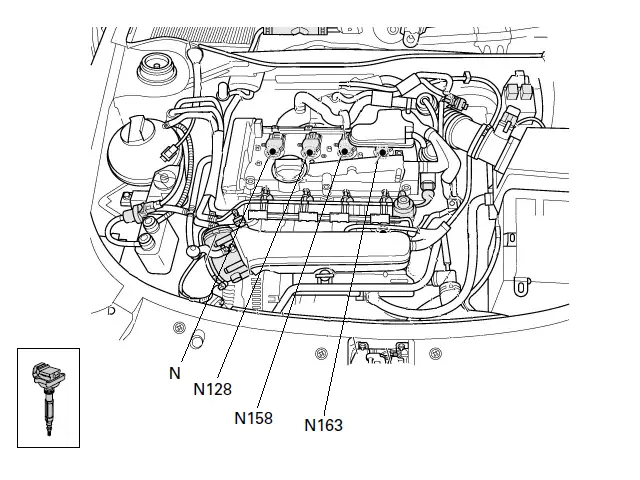
N, N128, N158, N163 - Ignition coils
The control unit controls the timing and duration of the spark production.
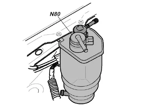
N80 - Valve for activated carbon tank
The electrovalve at rest is closed, the passage of vapors to the intake manifold opening when it is excited.
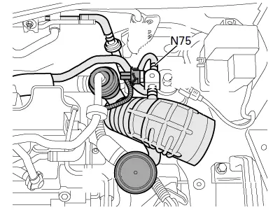
N75 - Boost pressure control solenoid valve
The control unit uses it to adjust the boost pressure by intervening on its opening time.
J338 - Throttle body control unit
G186 - Throttle actuator
The accelerator pedal position is transmitted by the controller to the G186.
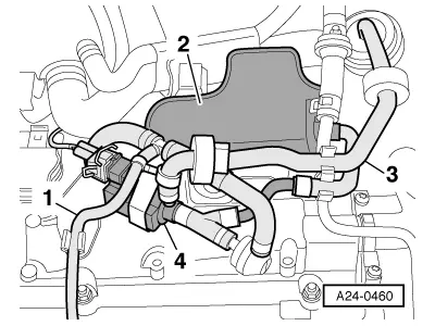
N249 - Air recycling valve for turbocharger
The control unit uses this valve during the deceleration phase in order to limit the slowing down of the turbine and thus reduce the “turbocompressor hole” effect.
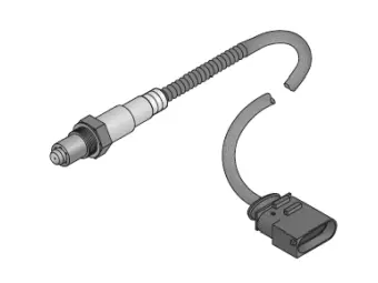
Z19 and Z29 - Heating for lambda probe
The lambda probes operate from 300 ° C, the control unit triggers their heating to bring them faster at this temperature.
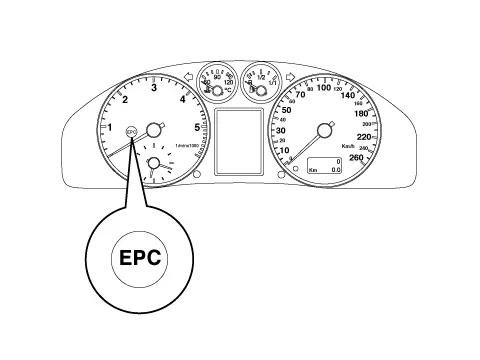
K132 - Electric accelerator control fault indicator
The control unit switches on the Electronic Power Control (EPC) indicator as soon as it detects an electric accelerator control fault.
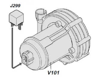
J299 - Secondary air pump relay
V101 - Secondary air pump motor
The control unit activates the secondary air pump motor, when necessary, via relay J299.
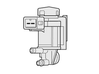
N112 - Secondary air injection valve
Its function is to create the air pressure necessary to allow the injection of air into the exhaust.
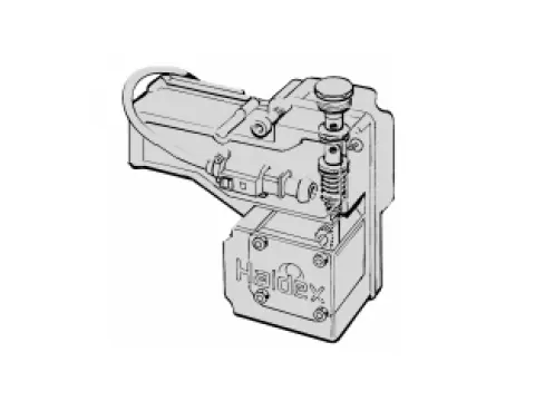
J492 - Haldex control unit
The control unit transmits information to the Haldex control unit, which uses it in its own process.
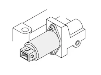
N205 - Variable valve timing solenoid valve
The control unit sends information to the solenoid valve to control oil pressure to the camshaft adjuster, changing the position of the tensioning piston.
Location of sensors and actuators
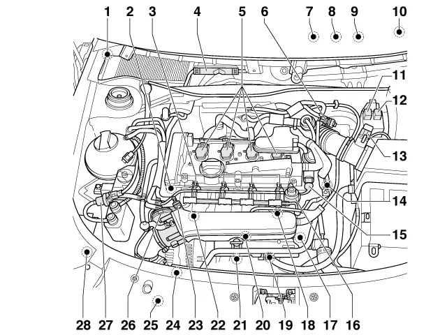
Location of sensors and actuators
| Number | Component / Function |
|---|---|
| 1 | G39 - Lambda sensor |
| 2 | G163 - Hall transmitter |
| 3 | Injectors: N30 - Cylinder 1 N31 - Cylinder 2 N32 - Cylinder 3 N33 - Cylinder 4 |
| 4 | J220 - Motronic engine control unit |
| 5 | Ignition coils: N - Cylinder 1 N128 - Cylinder 2 N158 - Cylinder 3 N163 - Cylinder 4 |
| 6 | N75 - Boost pressure control solenoid valve |
| 7 | G79 - Accelerator pedal position transmitter 1 G185 - Accelerator pedal position sensor 2 |
| 8 | F - Stop light switch F47 - Brake pedal switch |
| 9 | F36 - Clutch pedal contactor |
| 10 | Instrument cluster |
| 11 | J271 - Motronic system power relays |
| 12 | J299 - Secondary air pump relay |
| 13 | G70 - Mass air flow meter |
| 14 | G62 - Coolant temperature transmitter |
| 15 | N205 - Variable valve timing solenoid valve 1 |
| 16 | Fuel pressure regulator |
| 17 | G28 - Engine speed transmitter |
| 18 | G66 - Knock sensor 2 |
| 19 | N249 - Turbocharger air recirculation valve |
| 20 | 3-pin connector for G28 engine speed sensor, G61 knock sensor 1 and G66 knock sensor 2 |
| 21 | N112 - Secondary air injection valve |
| 22 | G61 - Knock sensor 1 |
| 23 | G42 - Intake air temperature transmitter |
| 24 | V101 - Secondary air pump motor |
| 25 | F88 - Power steering pressure switch |
| 26 | J338 - Throttle body control unit |
| 27 | N80 - Activated carbon tank solenoid valve 1 |
| 28 | G31 - Boost pressure transmitter |