Audi TT MK1 (8N) Haldex all-wheel drive
All-wheel drive with variable torque distribution and an electrohydraulically controlled, oil-bathed multi-plate coupling.
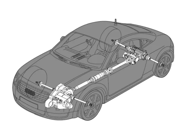
The Audi TT 8N quattro uses a first-generation Haldex all-wheel-drive system designed for its transversely mounted engine.
The front wheels are driven directly by the gearbox. An angle drive and a propeller shaft also transmit drive to the Haldex coupling, which is mounted ahead of the rear differential.
The coupling contains an oil-bathed multi-plate clutch. Hydraulic pressure applied to the plates modulates the torque transmitted to the rear wheels. Its operation combines a hydraulic mechanism that responds to the rotational speed difference between the axles with electronic control that adapts its action to the driving conditions.
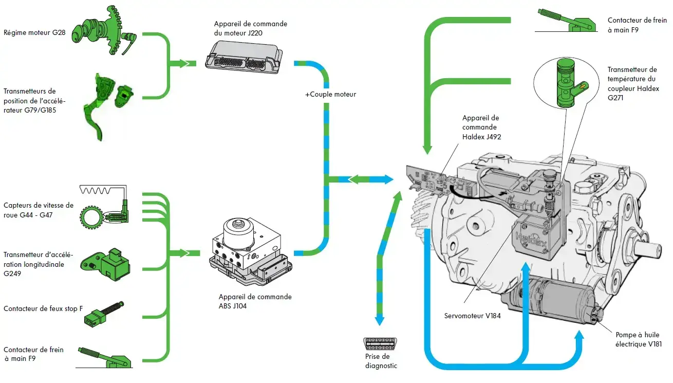
The control unit uses information including wheel speeds, engine torque and speed, accelerator position and ABS system signals. Torque distribution between the axles is therefore variable.
Diagram of the Haldex multi-plate coupling
The operation of the Haldex disc coupler is based on mechanical, hydraulic and electronic elements.
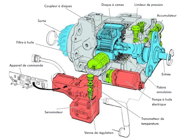
The mechanics, in blue on the diagram, consists essentially of moving elements:
- the input shaft
- the inner and outer discs
- the cam disc
- roller bearings with annular pistons
- the output shaft
The hydraulics, in green on the diagram, consists essentially of:
- pressure valves
- of the accumulator
- oil filter
- annular pistons
- of the control valve
The electronics, in red on the diagram, consists essentially of:
- electric oil pump
- the servomotor of the control valve
- the temperature transmitter
- the control unit
Mechanical part
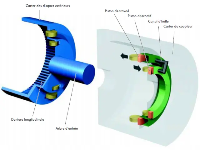
The input shaft of the coupler, shown in blue on the figure, is connected to the gimbal shaft. When the input shaft rotates, the roller bearings of the reciprocating piston and working piston as well as the outer discs are driven.
The output shaft, shown in red on the figure, constitutes a unit, from the cam disc to the drive pinion. The inner discs are also connected via a longitudinal toothing to the output shaft.
When accelerating, the input shaft rotates with the reciprocating piston roller bearing around the still stationary cam disc of the output shaft.
The roller bearing then follows the upward and downward movement of the cam disc.
These upward and downward movements are transmitted by the roller to the reciprocating piston.
The reciprocating piston is then set in motion and establishes an oil pressure.
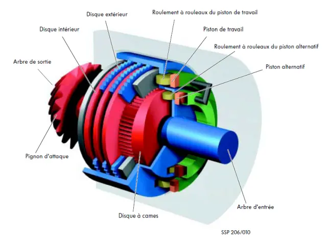
This oil pressure is conveyed through an oil channel to the working piston. It pushes the working piston to the left, against the roller of the bearing and the pressure plate of the disk package.
The package of disks is compressed.
The connection between the input shaft and the output shaft of the coupler is established, achieving all-wheel drive.
If there is a difference in speed between the front and rear gears, the outer disc housing rotates with the roller bearings around the output shaft, so that the reciprocating piston roller bearings roll on the cam disc. Due to the shape of the cam disc, the roller bearings describe an upward and downward movement and transmit this movement to the reciprocating piston housed in the housing.
The output shaft with the longitudinal toothing for the inner discs constitutes a unit with the cam disc and the drive pinion.
The outer disc housing with the longitudinal toothing for the outer discs and roller bearings forms a unit with the input shaft.
The lifting movement of the reciprocating piston generates an oil pressure acting via the oil channel on the working piston and pushing it to the left.
The pressure is transmitted by the roller bearings from the working piston via a pressure plate to the disk package.
The coupler closes and thus makes a connection between the front and rear trains.
Hydraulic section
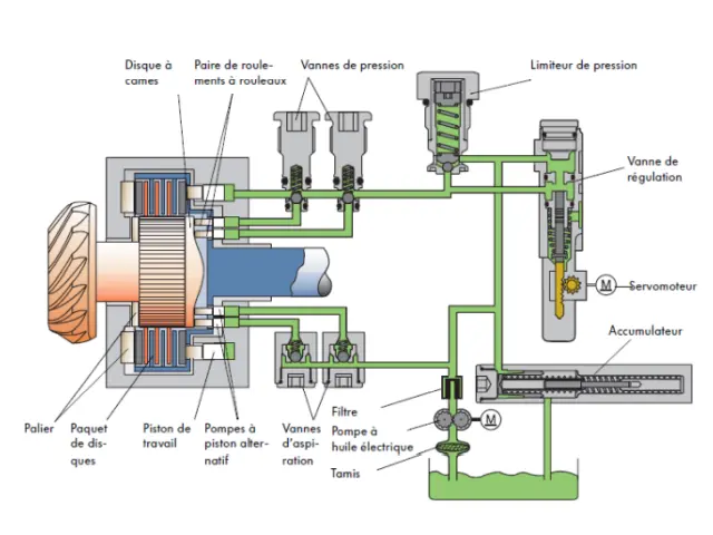
Representation of the pressure-free system
The pressure limiter determines the maximum pressure at the coupling discs.
The other components are presented below.
The establishment of the oil pressure at the reciprocating piston due to the difference in the speed of rotation of the input shaft (blue) and the output shaft with cam disc (red) was explained above.
This oil pressure is regulated by valves. The disc coupler can thus allow, in the open and almost closed state, a certain slippage.
For reasons of simplification, the operation is explained with an alternative piston. In fact, the coupler housing contains two reciprocating pistons, actuated by a pair of roller bearings.
Therefore there is a need for two suction valves and two pressure valves.
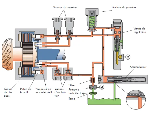
Setting the pressure of the electric pump (preload pressure)
An electric oil pump is electrically activated from an engine speed > 400/min.
The electric oil pump takes the hydraulic oil through a sieve from the pressure-free part of the coupler housing and pumps the oil through a filter through the suction valves to the reciprocating pistons.
The reciprocating pistons are thus supplied with oil and simultaneously brought in and held in support on the cam disc by the roller bearings.
Simultaneously, the oil arrives via the control valve and the pressure valves at the working piston, which in turn comes to rest. This preload pressure also removes the set of disks, allowing to obtain a fast response behavior of the coupler.
The preload pressure of 4 bar is defined by the accumulator, which also aims to smooth out pressure variations.
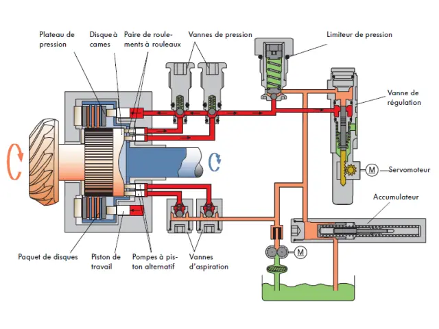
Pressure setting via reciprocating pistons (closed control valve)
The oil pressure generated by the reciprocating pistons is conveyed via the pressure valves to the working piston.
The disk packet is closed and thus provides a link between the input shaft (blue) and the output shaft (red).
The pressure at the discs is determined by the control valve. The servo motor, controlled by the Haldex coupler control unit, acts on the control valve. When the control valve is closed, the pressure at the discs is maximum. The maximum pressure is defined by the pressure limiter.
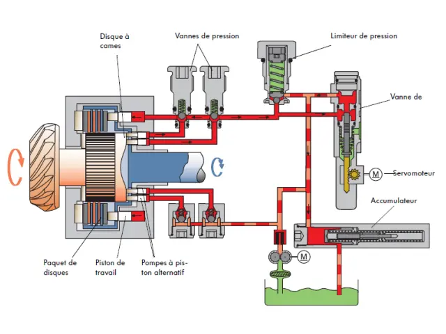
Pressure build-up by the reciprocating pistons (control valve one-third open)
The control valve is opened by about a third so that part of the oil can return via the accumulator into the oil sump.
The result is a reduction in pressure such that the coupler only allows a limited transmission of torque.
The coupler can thus, under given road conditions, allow a reduced all-wheel drive.
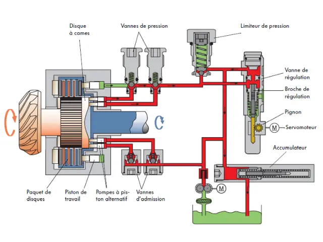
Pressure setting via reciprocating pistons (open control valve)
The control valve is open, allowing the oil to return to the oil sump via the control valve, passing through the accumulator.
There is therefore no pressure establishment at the working piston. The disc coupler is open and no torque transmission takes place.
The accumulator maintains the feed pressure in the return line of the control valve.
The feed pressure (4 bar) reigns in the return line from the control valve to the accumulator.
Electrical part
Synoptic of the system