Engines of the Audi TT MK1 (8N)
1.8 L turbo (150–240 hp) and 3.2 L V6 250 hp with transverse engine mounting.
The Audi TT was offered with two types of engines:
- a 1.8L turbo in-line four-cylinder engine
- a naturally aspirated 3.2L six-cylinder engine with a 15° V angle
The four-cylinder turbo engine, initially offered in 180 hp and 225 hp, was subsequently offered in different versions, offering powers of 150 hp, 163 hp, 190 hp and even 240 hp for the quattro sport version. These variations made it possible to meet different needs and requirements in terms of performance while maintaining the same basic architecture. The different versions of each of these declinations correspond to the evolutions necessary to comply with the changes in the anti-pollution standards.
The six-cylinder V engine, which appeared in 2003, offered a power of 250 hp.
These two types of engines were installed in a transverse position, which made it possible to optimize the space available in the engine compartment and improve the handling of the car.
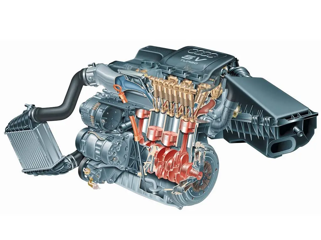
4-cylinder in-line 1.8L Turbo 150 to 190 hp
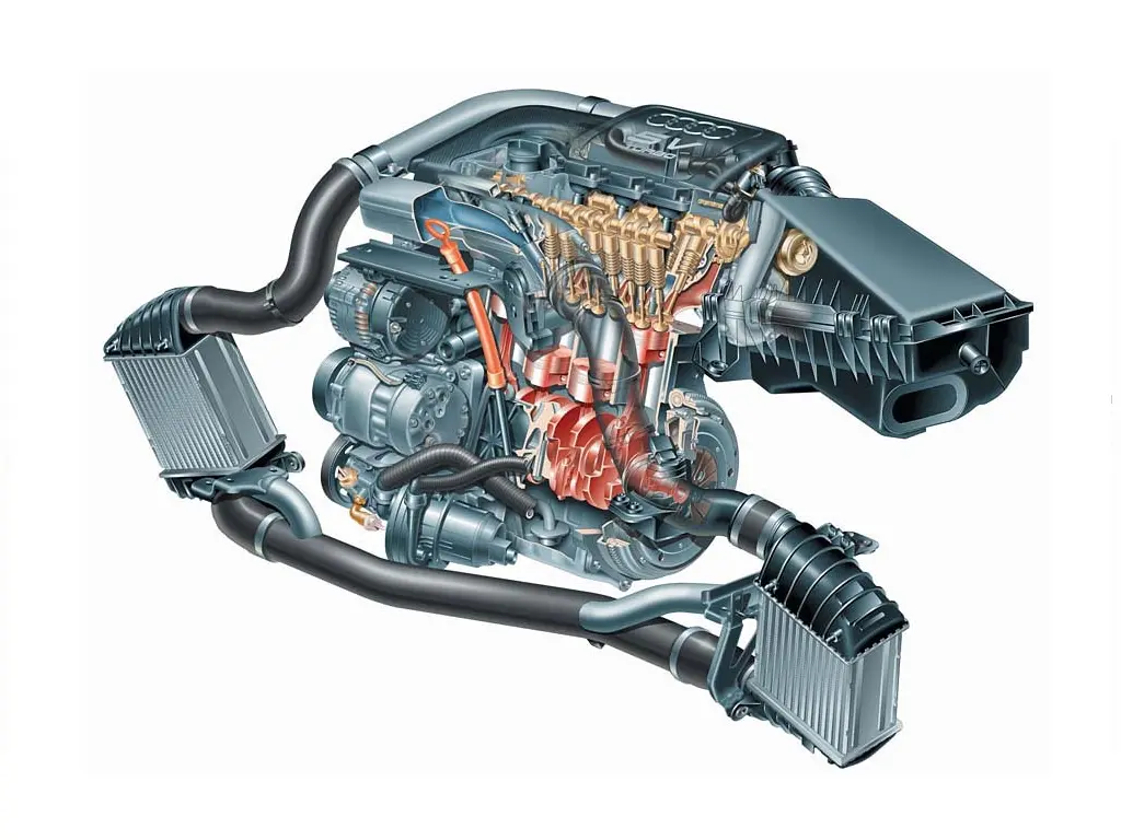
4-cylinder in-line 1.8L Turbo 225 hp
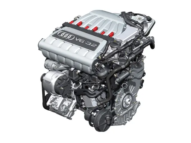
V6 at 15° 3.2L 250 hp"
Identification and main differences
The evolutions of the engines mainly respond to the evolutions of pollution standards.
| Type | Start date | End date | Emissions standard | Turbo | Catalyst control | Variable valve timing | Secondary Air System |
|---|---|---|---|---|---|---|---|
| 1.8 L Turbo - 150 hp | |||||||
| AUM | January 2001 | June 2006 | Euro 4 | KO3S |  |
|
|
| 1.8 L Turbo - 163 hp | |||||||
| BVP | September 2005 | June 2006 | Euro 4 | KO3S | |
|
|
| 1.8 L Turbo - 180 hp | |||||||
| AJQ | October 1998 | August 2000 | Euro 2 + D3 | KO3 | |||
| APP | September 1999 | September 2000 | Euro 2 + D4 | KO3 | |
|
|
| ARY | September 2000 | Mai 2005 | Euro 3 | KO3S | |
|
|
| AUQ | September 2000 | June 2005 | Euro 4 | KO3S | |
|
|
| ATC | 2000 | 2000 | TLEV | KO3 | |
|
|
| AWP | 2001 | 2005 | LEV | KO3S | |
|
|
| 1.8 L Turbo - 190 hp | |||||||
| BVR | September 2005 | June 2006 | Euro 4 | KO3S | |
|
|
| 1.8 L Turbo - 225 hp | |||||||
| APX | October 1998 | August 2001 | Euro 2 +D3 | KO4 | |
||
| BAM | September 2000 | September 2005 | Euro 3 | KO4 | |
|
|
| AMU | October 1998 | 2002 | TLEV | KO4 | |
|
|
| BEA | 2003 | September 2005 | LEV | KO4 | |
|
|
| 1.8 L Turbo - 240 hp | |||||||
| BFV | March 2005 | June 2006 | Euro 3 | KO4 | |
|
|
| 3.2 L Atmospheric - 250 HP | |||||||
| BHE | July 2003 | June 2006 | Euro 4 | - | |
|
|
| BPF | Mai 2004 | Mai 2006 | nc | - | |
|
|
Catalyst control
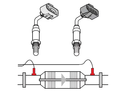
G39 - Lambda probe upstream of the catalyst
G130 - Lambda probe downstream of the catalyst
As part of the Euro 3 standard, an additional lambda probe (G130), located downstream of the catalyst, has been integrated into the exhaust system:
- The probe G39 upstream of the catalyst is used for air/fuel (wealth) dosing.
- The probe G130 downstream of the catalyst is used to control the operation of the catalyst.
During the diagnosis, the voltages of the probes upstream and downstream of the catalyst are compared by the motor control unit. We are talking here about a relationship between probe upstream and probe downstream of the catalyst.
If this ratio deviates from its set range, the engine management detects a malfunction of the catalyst. When the conditions of a fault are met, the fault memory stores the corresponding fault code.
The lambda control of the engine takes place even in case of failure of the probe downstream of the catalyst. Only the function of the catalyst can no longer be controlled in case of failure of the probe.
In the Motronic, control of the operation of the upstream catalyst probe is also eliminated.
Variable valve timing
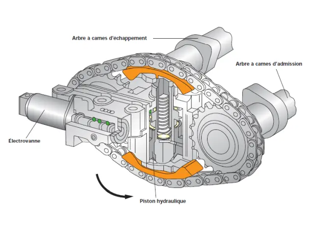
Variable valve timing
Variable valve timing was introduced to maintain engine power and torque while meeting the Euro 3 standard.
The valve timing system adjusts the intake valve opening and closing times according to engine speed and load, making the most of the advantages of the different camshaft overlap settings.
Intake camshaft timing is varied through the timing chain. A hydraulic piston in the adjuster changes the angular position of the intake camshaft relative to the exhaust camshaft.
At idle, the valve timing is in its basic position, favouring power.
From 1,300 rpm, the valve timing moves to the retarded position, favouring torque.
Finally, from 3,600 rpm, the valve timing returns to its basic position to favour power again.
Secondary Air System
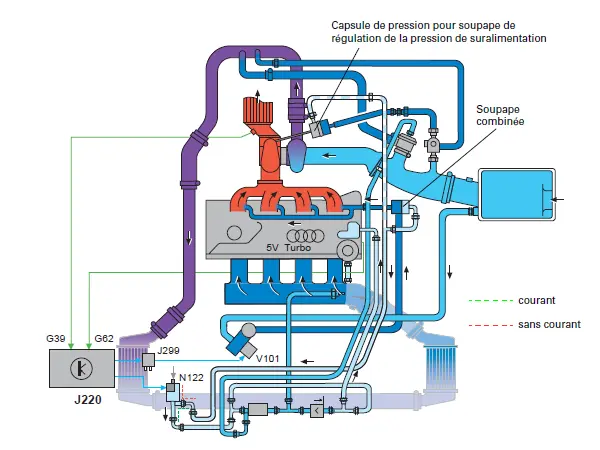
Secondary Air System
During the cold start phase, the proportion of unburned hydrocarbons is higher in the exhaust gases.
The secondary air injection system infuses air downstream of the exhaust valves to enrich the exhaust gases with oxygen.
This allows post-combustion of unburned hydrocarbons in the exhaust gases, thus improving their composition.
In addition, the working temperature of the catalyst is reached more quickly thanks to the release of heat attributable to this post-combustion.
As long as the secondary air injection system is operating, the pressure capsule of the boost pressure control valve, controlled by the valve N112, acts on the turbocharger waste-gate valve.
The exhaust gas flow is derived, not passing through the turbine wheel, up to the upper load range.
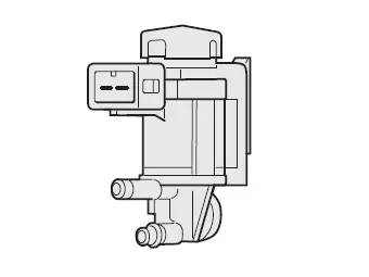
N112 - Secondary air injection valve
The secondary air injection valve is an electro-pneumatic valve, which is controlled by the Motronic control unit and controls the combined valve.
For the opening of the combined valve, it releases the depression from the intake tubing.
For closing, it releases atmospheric pressure.
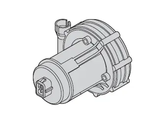
V101 - Secondary air pump
The J299 secondary air pump relay operated by the Motronic controller switches the current for the V101 secondary air pump motor. The fresh air mixed with the exhaust gases is sucked in by the secondary air pump from the air filter housing and released by the combined valve.